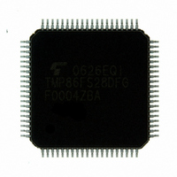
TMP86FS28DFG(JZ) Toshiba, TMP86FS28DFG(JZ) Datasheet - Page 43

TMP86FS28DFG(JZ)
Manufacturer Part Number
TMP86FS28DFG(JZ)
Description
IC MCU 8BIT FLASH 60KB 80-LQFP
Manufacturer
Toshiba
Series
TLCS-870/Cr
Datasheet
1.TMP86FS28DFGJZ.pdf
(272 pages)
Specifications of TMP86FS28DFG(JZ)
Core Processor
870/C
Core Size
8-Bit
Speed
16MHz
Connectivity
SIO, UART/USART
Peripherals
LCD, PWM, WDT
Number Of I /o
62
Program Memory Size
60KB (60K x 8)
Program Memory Type
FLASH
Ram Size
2K x 8
Voltage - Supply (vcc/vdd)
2.7 V ~ 5.5 V
Data Converters
A/D 8x10b
Oscillator Type
Internal
Operating Temperature
-40°C ~ 85°C
Package / Case
80-LQFP
Processor Series
TLCS-870
Core
870/C
Data Bus Width
8 bit
Data Ram Size
2 KB
Interface Type
SIO, UART
Maximum Clock Frequency
16 MHz
Number Of Programmable I/os
62
Number Of Timers
6
Maximum Operating Temperature
+ 85 C
Mounting Style
SMD/SMT
Development Tools By Supplier
BM1040R0A, BMP86A100010A, BMP86A100010B, BMP86A200010B, BMP86A200020A, BMP86A300010A, BMP86A300020A, BMP86A300030A, SW89CN0-ZCC, SW00MN0-ZCC
Minimum Operating Temperature
- 40 C
On-chip Adc
10 bit, 8 Channel
For Use With
BM1401W0A-G - FLASH WRITER ON-BOARD PROGRAMTMP89C900XBG - EMULATION CHIP TMP89F LQFP
Lead Free Status / RoHS Status
Lead free / RoHS Compliant
Eeprom Size
-
Lead Free Status / Rohs Status
Details
Other names
TMP86FS28DFGJZ
Available stocks
Company
Part Number
Manufacturer
Quantity
Price
- Current page: 43 of 272
- Download datasheet (3Mb)
2.3 Reset Circuit
2.3.1 External Reset Input
a watchdog timer reset and a system clock reset. Of these reset, the address trap reset, the watchdog timer and the
system clock reset are a malfunction reset. When the malfunction reset request is detected, reset occurs during the
maximum 24/fc[s].
ized when power is turned on. Therefore, reset may occur during maximum 24/fc[s] (1.5µs at 16.0 MHz) when
power is turned on.
The TMP86FS28DFG has four types of reset generation procedures: An external reset input, an address trap reset,
The malfunction reset circuit such as watchdog timer reset, address trap reset and system clock reset is not initial-
Table 2-3 shows on-chip hardware initialization by reset action.
Table 2-3 Initializing Internal Status by Reset Action
RESET
Program counter
Stack pointer
General-purpose registers
Jump status flag
Zero flag
Carry flag
Half carry flag
Sign flag
Overflow flag
Interrupt master enable flag
Interrupt individual enable flags
Interrupt latches
age within the operating voltage range and oscillation stable, a reset is applied and the internal state is initial-
ized.
vector address stored at addresses FFFEH to FFFFH.
(W, A, B, C, D, E, H, L, IX, IY)
The
When the
When the
RESET
On-chip Hardware
VDD
RESET
RESET
pin contains a Schmitt trigger (Hysteresis) with an internal pull-up resistor.
pin is held at “L” level for at least 3 machine cycles (12/fc [s]) with the power supply volt-
pin input goes high, the reset operation is released and the program execution starts at the
(IMF)
(PC)
(SP)
(CF)
(HF)
(SF)
(VF)
(EF)
(ZF)
(JF)
(IL)
Figure 2-15 Reset Circuit
Not initialized
Not initialized
Not initialized
Not initialized
Not initialized
Not initialized
Not initialized
Not initialized
Initial Value
(FFFEH)
Internal reset
0
0
0
reset output
Malfunction
circuit
Page 31
Prescaler and divider of timing generator
Watchdog timer
Output latches of I/O ports
Control registers
LCD data buffer
RAM
On-chip Hardware
Watchdog timer reset
System clock reset
Address trap reset
Refer to I/O port circuitry
Refer to each of control
register
Not initialized
Not initialized
Initial Value
Enable
0
TMP86FS28DFG
Related parts for TMP86FS28DFG(JZ)
Image
Part Number
Description
Manufacturer
Datasheet
Request
R
Part Number:
Description:
Toshiba Semiconductor [TOSHIBA IGBT Module Silicon N Channel IGBT]
Manufacturer:
TOSHIBA Semiconductor CORPORATION
Datasheet:
Part Number:
Description:
TOSHIBA GTR MODULE SILICON NPN TRIPLE DIFFUSED TYPE
Manufacturer:
TOSHIBA Semiconductor CORPORATION
Datasheet:
Part Number:
Description:
TOSHIBA GTR Module Silicon N Channel IGBT
Manufacturer:
TOSHIBA Semiconductor CORPORATION
Datasheet:
Part Number:
Description:
TOSHIBA Intelligent Power Module Silicon N Channel IGBT
Manufacturer:
TOSHIBA Semiconductor CORPORATION
Datasheet:
Part Number:
Description:
TOSHIBA INTELLIGENT POWER MODULE SILICON N CHANNEL LGBT
Manufacturer:
TOSHIBA Semiconductor CORPORATION
Datasheet:
Part Number:
Description:
TOSHIBA IGBT Module Silicon N Channel IGBT
Manufacturer:
TOSHIBA Semiconductor CORPORATION
Datasheet:
Part Number:
Description:
TOSHIBA GTR MODULE SILICON N−CHANNEL IGBT
Manufacturer:
TOSHIBA Semiconductor CORPORATION
Datasheet:
Part Number:
Description:
TOSHIBA Intelligent Power Module Silicon N Channel IGBT
Manufacturer:
TOSHIBA Semiconductor CORPORATION
Datasheet:
Part Number:
Description:
TOSHIBA GTR Module Silicon N Channel IGBT
Manufacturer:
TOSHIBA Semiconductor CORPORATION
Datasheet:
Part Number:
Description:
TOSHIBA INTELLIGENT POWER MODULE
Manufacturer:
TOSHIBA Semiconductor CORPORATION
Datasheet:
Part Number:
Description:
TOSHIBA Intelligent Power Module Silicon N Channel IGBT
Manufacturer:
TOSHIBA Semiconductor CORPORATION
Datasheet:
Part Number:
Description:
TOSHIBA Intelligent Power Module Silicon N Channel IGBT
Manufacturer:
TOSHIBA Semiconductor CORPORATION
Datasheet:
Part Number:
Description:
TOSHIBA IGBT Module Silicon N Channel IGBT
Manufacturer:
TOSHIBA Semiconductor CORPORATION
Datasheet:
Part Number:
Description:
TOSHIBA Intelligent Power Module Silicon N Channel IGBT
Manufacturer:
TOSHIBA Semiconductor CORPORATION
Datasheet:
Part Number:
Description:
Toshiba Semiconductor [SILICON N CHANNEL 1GBT]
Manufacturer:
TOSHIBA Semiconductor CORPORATION
Datasheet:


