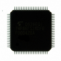
TMP86FS28DFG(JZ) Toshiba, TMP86FS28DFG(JZ) Datasheet - Page 262

TMP86FS28DFG(JZ)
Manufacturer Part Number
TMP86FS28DFG(JZ)
Description
IC MCU 8BIT FLASH 60KB 80-LQFP
Manufacturer
Toshiba
Series
TLCS-870/Cr
Datasheet
1.TMP86FS28DFGJZ.pdf
(272 pages)
Specifications of TMP86FS28DFG(JZ)
Core Processor
870/C
Core Size
8-Bit
Speed
16MHz
Connectivity
SIO, UART/USART
Peripherals
LCD, PWM, WDT
Number Of I /o
62
Program Memory Size
60KB (60K x 8)
Program Memory Type
FLASH
Ram Size
2K x 8
Voltage - Supply (vcc/vdd)
2.7 V ~ 5.5 V
Data Converters
A/D 8x10b
Oscillator Type
Internal
Operating Temperature
-40°C ~ 85°C
Package / Case
80-LQFP
Processor Series
TLCS-870
Core
870/C
Data Bus Width
8 bit
Data Ram Size
2 KB
Interface Type
SIO, UART
Maximum Clock Frequency
16 MHz
Number Of Programmable I/os
62
Number Of Timers
6
Maximum Operating Temperature
+ 85 C
Mounting Style
SMD/SMT
Development Tools By Supplier
BM1040R0A, BMP86A100010A, BMP86A100010B, BMP86A200010B, BMP86A200020A, BMP86A300010A, BMP86A300020A, BMP86A300030A, SW89CN0-ZCC, SW00MN0-ZCC
Minimum Operating Temperature
- 40 C
On-chip Adc
10 bit, 8 Channel
For Use With
BM1401W0A-G - FLASH WRITER ON-BOARD PROGRAMTMP89C900XBG - EMULATION CHIP TMP89F LQFP
Lead Free Status / RoHS Status
Lead free / RoHS Compliant
Eeprom Size
-
Lead Free Status / Rohs Status
Details
Other names
TMP86FS28DFGJZ
Available stocks
Company
Part Number
Manufacturer
Quantity
Price
- Current page: 262 of 272
- Download datasheet (3Mb)
20.2 Operating Condition
20.2 Operating Condition
Supply voltage
Input high level
Input low level
Clock frequency
Supply voltage
Input high level
Input low level
Clock frequency
LCD reference voltage
range
Capacity for LCD
booster circuit
20.2.1 MCU mode (Flash Programming or erasing)
20.2.2 MCU mode (Except Flash Programming or erasing)
while maintaining its quality. If the device is used outside the range of Operating Conditions (power supply voltage,
operating temperature range, or AC/DC rated values), it may operate erratically. Therefore, when designing your
application equipment, always make sure its intended working conditions will not exceed the range of Operating
Conditions.
Parameter
Parameter
The Operating Conditions show the conditions under which the device be used in order for it to operate normally
Note 1: When the supply voltage is V
Symbol
Symbol
C
V
V
V
V
V
V
V
V
V
V
V
V
V1
LCD
fc
fc
fs
DD
IH1
IH2
DD
IH1
IH2
IH3
IL1
IL2
IL1
IL2
IL3
Except hysteresis input
Hysteresis input
Except hysteresis input
Hysteresis input
XIN, XOUT
XTIN, XTOUT
Except hysteresis input
Hysteresis input
Except hysteresis input
Hysteresis input
XIN, XOUT
Pins
Pins
DD
< 3.0V, the operating tempreture is Topr= -20 to 85 °
Page 250
fc = 16 MHz
fc = 8 MHz
fs =
32.768 kHz
V
V
V
V
V
V
V
LCD booster circuit enable
(V3 ≥ V
DD
DD
DD
DD
DD
DD
DD
≥ 4.5 V
< 4.5 V
≥ 4.5 V
< 4.5 V
= 2.7 V to 5.5 V
= 4.0 V to 5.5 V
= 2.7 V to 5.5 V
NORMAL1, 2 modes
V
V
DD
DD
DD
)
≥ 4.5 V
≥ 4.5 V
Condition
NORMAL1, 2 mode
IDLE0, 1, 2 mode
NORMAL1, 2 mode
IDLE0, 1, 2 mode
SLOW1, 2 mode
SLEEP0, 1, 2 mode
STOP mode
Ratings
V
V
DD
DD
V
V
V
2.7(Note1)
Min
4.5
1.0
× 0.70
× 0.75
DD
DD
DD
0
30.0
Min
4.0
1.0
0.9
0.1
× 0.70
× 0.75
× 0.90
0
(V
(V
C.
SS
SS
= 0 V, Topr = -10 to 40°C)
= 0 V, Topr = −40 to 85°C)
V
V
DD
DD
V
V
V
Max
16.0
V
DD
DD
DD
5.5
TMP86FS28DFG
× 0.30
× 0.25
DD
Max
V
16.0
34.0
0.47
5.5
8.0
1.8
× 0.30
× 0.25
× 0.10
DD
MHz
Unit
MHz
Unit
kHz
V
uF
V
V
Related parts for TMP86FS28DFG(JZ)
Image
Part Number
Description
Manufacturer
Datasheet
Request
R
Part Number:
Description:
Toshiba Semiconductor [TOSHIBA IGBT Module Silicon N Channel IGBT]
Manufacturer:
TOSHIBA Semiconductor CORPORATION
Datasheet:
Part Number:
Description:
TOSHIBA GTR MODULE SILICON NPN TRIPLE DIFFUSED TYPE
Manufacturer:
TOSHIBA Semiconductor CORPORATION
Datasheet:
Part Number:
Description:
TOSHIBA GTR Module Silicon N Channel IGBT
Manufacturer:
TOSHIBA Semiconductor CORPORATION
Datasheet:
Part Number:
Description:
TOSHIBA Intelligent Power Module Silicon N Channel IGBT
Manufacturer:
TOSHIBA Semiconductor CORPORATION
Datasheet:
Part Number:
Description:
TOSHIBA INTELLIGENT POWER MODULE SILICON N CHANNEL LGBT
Manufacturer:
TOSHIBA Semiconductor CORPORATION
Datasheet:
Part Number:
Description:
TOSHIBA IGBT Module Silicon N Channel IGBT
Manufacturer:
TOSHIBA Semiconductor CORPORATION
Datasheet:
Part Number:
Description:
TOSHIBA GTR MODULE SILICON N−CHANNEL IGBT
Manufacturer:
TOSHIBA Semiconductor CORPORATION
Datasheet:
Part Number:
Description:
TOSHIBA Intelligent Power Module Silicon N Channel IGBT
Manufacturer:
TOSHIBA Semiconductor CORPORATION
Datasheet:
Part Number:
Description:
TOSHIBA GTR Module Silicon N Channel IGBT
Manufacturer:
TOSHIBA Semiconductor CORPORATION
Datasheet:
Part Number:
Description:
TOSHIBA INTELLIGENT POWER MODULE
Manufacturer:
TOSHIBA Semiconductor CORPORATION
Datasheet:
Part Number:
Description:
TOSHIBA Intelligent Power Module Silicon N Channel IGBT
Manufacturer:
TOSHIBA Semiconductor CORPORATION
Datasheet:
Part Number:
Description:
TOSHIBA Intelligent Power Module Silicon N Channel IGBT
Manufacturer:
TOSHIBA Semiconductor CORPORATION
Datasheet:
Part Number:
Description:
TOSHIBA IGBT Module Silicon N Channel IGBT
Manufacturer:
TOSHIBA Semiconductor CORPORATION
Datasheet:
Part Number:
Description:
TOSHIBA Intelligent Power Module Silicon N Channel IGBT
Manufacturer:
TOSHIBA Semiconductor CORPORATION
Datasheet:
Part Number:
Description:
Toshiba Semiconductor [SILICON N CHANNEL 1GBT]
Manufacturer:
TOSHIBA Semiconductor CORPORATION
Datasheet:


