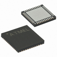
ATMEGA1284P-MUR Atmel, ATMEGA1284P-MUR Datasheet - Page 35

ATMEGA1284P-MUR
Manufacturer Part Number
ATMEGA1284P-MUR
Description
MCU AVR 128KB FLASH 20MHZ 44VQFN
Manufacturer
Atmel
Series
AVR® ATmegar
Specifications of ATMEGA1284P-MUR
Core Processor
AVR
Core Size
8-Bit
Speed
20MHz
Connectivity
I²C, SPI, UART/USART
Peripherals
Brown-out Detect/Reset, POR, PWM, WDT
Number Of I /o
32
Program Memory Size
128KB (64K x 16)
Program Memory Type
FLASH
Eeprom Size
4K x 8
Ram Size
16K x 8
Voltage - Supply (vcc/vdd)
1.8 V ~ 5.5 V
Data Converters
A/D 8x10b
Oscillator Type
Internal
Operating Temperature
-40°C ~ 85°C
Package / Case
44-VQFN Exposed Pad
For Use With
ATSTK600 - DEV KIT FOR AVR/AVR32
Lead Free Status / RoHS Status
Lead free / RoHS Compliant
- Current page: 35 of 581
- Download datasheet (27Mb)
8.5
8272A–AVR–01/10
Low Frequency Crystal Oscillator
Table 8-6.
Notes:
The Low-frequency Crystal Oscillator is optimized for use with a 32.768 kHz watch crystal.
When selecting crystals, load capasitance and crystal’s Equivalent Series Resistance, ESR
must be taken into consideration. Both values are specified by the crystal vendor.
ATmega164A/164PA/324A/324PA/644A/644PA/1284/1284P oscillator is optimized for very low
power consumption, and thus when selecting crystals, see
ESR recommendations on 9 pF and 12.5 pF crystals.
Table 8-7.
Note:
The Low-frequency Crystal Oscillator provides an internal load capacitance, see
35
Table 8-8.
The capacitance (Ce + Ci) needed at each TOSC pin can be calculated by using:
where:
164A/164PA/324A/324PA/644A/644PA/1284/1284P
Oscillator Source /
Power Conditions
Ceramic resonator, fast
rising power
Ceramic resonator, slowly
rising power
Crystal Oscillator, BOD
enabled
Crystal Oscillator, fast
rising power
Crystal Oscillator, slowly
rising power
ATmega164A/164PA/324A/324PA/
at each TOSC pin.
644A/644PA/1284/1284P
1. These options should only be used when not operating close to the maximum frequency of the
2. These options are intended for use with ceramic resonators and will ensure frequency stability
1. Maximum ESR is typical value based on characterization
device, and only if frequency stability at start-up is not important for the application. These
options are not suitable for crystals.
at start-up. They can also be used with crystals when not operating close to the maximum fre-
quency of the device, and if frequency stability at start-up is not important for the application.
Device
Start-up Times for the Full Swing Crystal Oscillator Clock Selection
Maximum ESR Recommendation for 32.768 kHz Watch Crystal
Capacitance for Low-frequency Oscillator
Crystal CL (pF)
12.5
9.0
Start-up Time from
Power-down and
Power-save
16K CK
16K CK
16K CK
32kHz Osc. Type
1K CK
1K CK
System Osc.
Ce
Timer Osc.
+
Ci
=
2 CL
⋅
Additional Delay
–
14CK + 4.1 ms
14CK + 65 ms
14CK + 4.1 ms
14CK + 65 ms
C
(V
Cap (Xtal1/Tosc1)
from Reset
s
CC
14CK
Table 8-7 on page 35
= 5.0V)
18 pF
6 pF
Max ESR [kΩ]
(2)
(2)
65
30
CKSEL0
Cap (Xtal2/Tosc2)
(1)
0
1
1
1
1
Table on page
for maximum
8 pF
6 pF
SUT1..0
11
00
01
10
11
35
Related parts for ATMEGA1284P-MUR
Image
Part Number
Description
Manufacturer
Datasheet
Request
R

Part Number:
Description:
Manufacturer:
ATMEL Corporation
Datasheet:

Part Number:
Description:
Microcontroller with 128K bytes In-system programmable flash, 8 MHz, power supply =2.7 - 5.5V
Manufacturer:
ATMEL Corporation
Datasheet:

Part Number:
Description:
IC AVR MCU 128K 16MHZ 5V 64TQFP
Manufacturer:
Atmel
Datasheet:

Part Number:
Description:
IC AVR MCU 128K 16MHZ 5V 64-QFN
Manufacturer:
Atmel
Datasheet:

Part Number:
Description:
IC AVR MCU 128K 16MHZ COM 64-QFN
Manufacturer:
Atmel
Datasheet:

Part Number:
Description:
IC AVR MCU 128K 16MHZ 64-TQFP
Manufacturer:
Atmel
Datasheet:

Part Number:
Description:
IC AVR MCU 128K 16MHZ 64-TQFP
Manufacturer:
Atmel
Datasheet:

Part Number:
Description:
IC AVR MCU 128K 16MHZ IND 64-QFN
Manufacturer:
Atmel
Datasheet:

Part Number:
Description:
MCU AVR 128KB FLASH 16MHZ 64TQFP
Manufacturer:
Atmel
Datasheet:

Part Number:
Description:
MCU AVR 128KB FLASH 16MHZ 64QFN
Manufacturer:
Atmel
Datasheet:

Part Number:
Description:
MCU AVR 128KB FLASH 16MHZ 64TQFP
Manufacturer:
Atmel
Datasheet:


