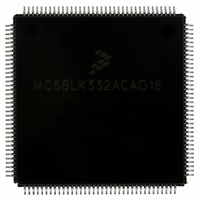
MC68LK332ACAG16 Freescale Semiconductor, MC68LK332ACAG16 Datasheet - Page 83

MC68LK332ACAG16
Manufacturer Part Number
MC68LK332ACAG16
Description
IC MCU 32BIT LV AMASK 144-LQFP
Manufacturer
Freescale Semiconductor
Series
M683xxr
Specifications of MC68LK332ACAG16
Core Processor
CPU32
Core Size
32-Bit
Speed
16.78MHz
Connectivity
EBI/EMI, SCI, SPI, UART/USART
Peripherals
POR, PWM, WDT
Number Of I /o
15
Program Memory Type
ROMless
Ram Size
2K x 8
Voltage - Supply (vcc/vdd)
3 V ~ 3.6 V
Oscillator Type
Internal
Operating Temperature
-40°C ~ 85°C
Package / Case
144-LQFP
Processor Series
M683xx
Core
CPU32
Data Bus Width
32 bit
Maximum Clock Frequency
16 MHz
Maximum Operating Temperature
+ 85 C
Mounting Style
SMD/SMT
Interface Type
QSPI, SCI, UART
Minimum Operating Temperature
- 40 C
No. Of I/o's
15
Ram Memory Size
2KB
Cpu Speed
16MHz
No. Of Timers
16
Embedded Interface Type
QSPI, SCI, UART
Digital Ic Case Style
LQFP
Rohs Compliant
Yes
Data Ram Size
2 KB
Number Of Programmable I/os
15
Number Of Timers
16
Cpu Family
68K/M683xx
Device Core
ColdFire
Device Core Size
32b
Frequency (max)
16MHz
Program Memory Size
Not Required
Total Internal Ram Size
2KB
# I/os (max)
15
Number Of Timers - General Purpose
16
Operating Supply Voltage (typ)
5V
Instruction Set Architecture
RISC
Operating Temp Range
-40C to 85C
Operating Temperature Classification
Industrial
Mounting
Surface Mount
Pin Count
144
Package Type
LQFP
Lead Free Status / RoHS Status
Lead free / RoHS Compliant
Eeprom Size
-
Program Memory Size
-
Data Converters
-
Lead Free Status / Rohs Status
Lead free / RoHS Compliant
Available stocks
Company
Part Number
Manufacturer
Quantity
Price
Company:
Part Number:
MC68LK332ACAG16
Manufacturer:
MOTOLOLA
Quantity:
1 045
Company:
Part Number:
MC68LK332ACAG16
Manufacturer:
Freescale Semiconductor
Quantity:
10 000
Part Number:
MC68LK332ACAG16
Manufacturer:
FREESCALE
Quantity:
20 000
IDLE — Idle-Line Detected Flag
OR — Overrun Error Flag
NF — Noise Error Flag
FE — Framing Error Flag
PF — Parity Error Flag
SCDR — SCI Data Register
MC68332
MC68332TS/D
RESET:
15
0
0
IDLE is disabled when RWU in SCCR1 is set. IDLE is set when the SCI receiver detects the idle-line
condition specified by ILT in SCCR1. If cleared, IDLE will not set again until after RDRF is set. RDRF
is set when a break is received, so that a subsequent idle line can be detected.
OR is set when a new byte is ready to be transferred from the receive serial shifter to the RDR, and
RDRF is still set. Data transfer is inhibited until OR is cleared. Previous data in RDR remains valid, but
data received during overrun condition (including the byte that set OR) is lost.
NF is set when the SCI receiver detects noise on a valid start bit, on any data bit, or on a stop bit. It is
not set by noise on the idle line or on invalid start bits. Each bit is sampled three times. If none of the
three samples are the same logic level, the majority value is used for the received data value, and NF
is set. NF is not set until an entire frame is received and RDRF is set.
FE is set when the SCI receiver detects a zero where a stop bit was to have occurred. FE is not set until
the entire frame is received and RDRF is set. A break can also cause FE to be set. It is possible to miss
a framing error if RXD happens to be at logic level one at the time the stop bit is expected.
PF is set when the SCI receiver detects a parity error. PF is not set until the entire frame is received and
RDRF is set.
SCDR contains two data registers at the same address. Receive data register (RDR) is a read-only reg-
ister that contains data received by the SCI. The data comes into the receive serial shifter and is trans-
ferred to RDR. Transmit data register (TDR) is a write-only register that contains data to be transmitted.
The data is first written to TDR, then transferred to the transmit serial shifter, where additional format
bits are added before transmission. R[7:0]/T[7:0] contain either the first eight data bits received when
SCDR is read, or the first eight data bits to be transmitted when SCDR is written. R8/T8 are used when
the SCI is configured for 9-bit operation. When it is configured for 8-bit operation, they have no meaning
or effect.
0 = SCI receiver did not detect an idle-line condition.
1 = SCI receiver detected an idle-line condition.
0 = RDRF is cleared before new data arrives.
1 = RDRF is not cleared before new data arrives.
0 = No noise detected on the received data
1 = Noise occurred on the received data
0 = No framing error on the received data.
1 = Framing error or break occurred on the received data.
0 = No parity error on the received data
1 = Parity error occurred on the received data
14
0
0
13
0
0
12
0
0
Freescale Semiconductor, Inc.
11
For More Information On This Product,
0
0
10
0
0
Go to: www.freescale.com
9
0
0
R8/T8
U
8
R7/T7
7
U
R6/T6
U
6
R5/T5
U
5
R4/T4
U
4
R3/T3
U
3
R2/T2
U
2
MOTOROLA
R1/T1
$YFFC0E
U
1
R0/T0
0
U
83


