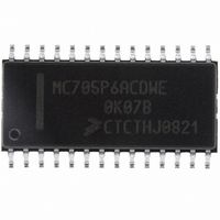
MC705P6ACDWE Freescale Semiconductor, MC705P6ACDWE Datasheet - Page 59

MC705P6ACDWE
Manufacturer Part Number
MC705P6ACDWE
Description
IC MCU 176 BYTES RAM 28-SOIC
Manufacturer
Freescale Semiconductor
Series
HC05r
Datasheet
1.MC705P6ACDWE.pdf
(98 pages)
Specifications of MC705P6ACDWE
Core Processor
HC05
Core Size
8-Bit
Speed
2.1MHz
Connectivity
SIO
Peripherals
POR, WDT
Number Of I /o
21
Program Memory Size
4.5KB (4.5K x 8)
Program Memory Type
OTP
Ram Size
176 x 8
Voltage - Supply (vcc/vdd)
3 V ~ 5.5 V
Data Converters
A/D 4x8b
Oscillator Type
Internal
Operating Temperature
-40°C ~ 85°C
Package / Case
28-SOIC (7.5mm Width)
Processor Series
HC705P
Core
HC05
Data Bus Width
8 bit
Data Ram Size
176 B
Maximum Clock Frequency
2.1 MHz
Number Of Programmable I/os
21
Number Of Timers
1
Maximum Operating Temperature
+ 85 C
Mounting Style
SMD/SMT
Minimum Operating Temperature
- 40 C
On-chip Adc
8 bit, 4 Channel
Lead Free Status / RoHS Status
Lead free / RoHS Compliant
Eeprom Size
-
Lead Free Status / Rohs Status
Details
Available stocks
Company
Part Number
Manufacturer
Quantity
Price
Company:
Part Number:
MC705P6ACDWE
Manufacturer:
Freescale Semiconductor
Quantity:
135
Part Number:
MC705P6ACDWE
Manufacturer:
FREESCALE
Quantity:
20 000
10.6 EPROM Bootloader
Three port pins are associated with bootloader control functions: PC3, PC4, and PC6.
summarizes their functionality.
10.7 Programming from an External Memory Device
In this programming mode, PC5 must be connected to V
programming mode. The programming circuit shown in
address the memory device containing the code to be copied. This counter requires a clock and a reset
function. The 12-bit counter can address up to 4 Kbytes of memory, which means that a port pin has to
be used to address the remaining 4 K of the 8-K memory space.
The following procedure explains how to use the programming circuit shown in
program from an external memory device into the MCU’s EPROM:
Freescale Semiconductor
10. When complete, close the RESET switch to force the MCU into the reset state.
11. Turn off the V
12. Turn off the V
13. Remove device(s).
1. Program a 2764-type EPROM device with the desired instructions and data. Code programmed
2. Install the programmed 2764 device into the programming circuit.
3. Install the MC68HC705P6A to be programmed into the programming circuit.
4. Set the PROGRAM and/or VERIFY switches for the desired operation (an open switch is the active
5. Make sure that the V
6. Apply the V
7. Apply the V
8. Open the RESET switch to allow the MCU to come out of reset and begin execution of the software
9. Wait for programming and/or verification to complete (about 40 seconds). The PROGRAM LED will
into the 2764 must appear at the same addresses desired in the MC68HC705P6A. Therefore, the
page zero code must start at $0020 and end at $004F, the main body of code must start at $0100
and end at $12FF, and the user vectors must start at $1FF0 and end at $1FFF.
state) and close the RESET switch to hold the MCU in reset.
in its internal bootloader ROM.
light during programming and the VERIFY LED will light if verification was requested and was
successful.
DD
PP
PP
DD
PC6
source to the programming circuit.
source to the programming circuit.
1
1
1
source.
source.
MC68HC705P6A Advance Information Data Sheet, Rev. 2.1
The MOR data must appear at $1EFF and $1F00.
PP
PC4
source is OFF.
1
1
0
Table 10-2. Bootloader Control Pins
PC3
1
0
0
NOTE
Dump MCU EPROM to port A
Figure 10-2
SS
. PC4 and PC3 are used to select the
Program/verify
Verify only
Mode
uses an external 12-bit counter to
Figure 10-2
Table 10-2
EPROM Bootloader
to copy a user
59


