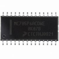
MC705P6ACDWE Freescale Semiconductor, MC705P6ACDWE Datasheet - Page 28

MC705P6ACDWE
Manufacturer Part Number
MC705P6ACDWE
Description
IC MCU 176 BYTES RAM 28-SOIC
Manufacturer
Freescale Semiconductor
Series
HC05r
Datasheet
1.MC705P6ACDWE.pdf
(98 pages)
Specifications of MC705P6ACDWE
Core Processor
HC05
Core Size
8-Bit
Speed
2.1MHz
Connectivity
SIO
Peripherals
POR, WDT
Number Of I /o
21
Program Memory Size
4.5KB (4.5K x 8)
Program Memory Type
OTP
Ram Size
176 x 8
Voltage - Supply (vcc/vdd)
3 V ~ 5.5 V
Data Converters
A/D 4x8b
Oscillator Type
Internal
Operating Temperature
-40°C ~ 85°C
Package / Case
28-SOIC (7.5mm Width)
Processor Series
HC705P
Core
HC05
Data Bus Width
8 bit
Data Ram Size
176 B
Maximum Clock Frequency
2.1 MHz
Number Of Programmable I/os
21
Number Of Timers
1
Maximum Operating Temperature
+ 85 C
Mounting Style
SMD/SMT
Minimum Operating Temperature
- 40 C
On-chip Adc
8 bit, 4 Channel
Lead Free Status / RoHS Status
Lead free / RoHS Compliant
Eeprom Size
-
Lead Free Status / Rohs Status
Details
Available stocks
Company
Part Number
Manufacturer
Quantity
Price
Company:
Part Number:
MC705P6ACDWE
Manufacturer:
Freescale Semiconductor
Quantity:
135
Part Number:
MC705P6ACDWE
Manufacturer:
FREESCALE
Quantity:
20 000
Operating Modes
3.4 Low-Power Modes
The MC68HC705P6A is capable of running in a low-power mode in each of its configurations. The WAIT
and STOP instructions provide three modes that reduce the power required for the MCU by stopping
various internal clocks and/or the on-chip oscillator. The SWAIT bit in the MOR is used to modify the
behavior of the STOP instruction from stop mode to halt mode. The flow of the stop, halt, and wait modes
is shown in
3.4.1 STOP Instruction
The STOP instruction can result in one of two modes of operation depending on the state of the SWAIT
bit in the MOR. If the SWAIT bit is clear, the STOP instruction will behave like a normal STOP instruction
in the M68HC05 Family and place the MCU in stop mode. If the SWAIT bit in the MOR is set, the STOP
instruction will behave like a WAIT instruction (with the exception of a brief delay at startup) and place the
MCU in halt mode.
3.4.1.1 Stop Mode
Execution of the STOP instruction when the SWAIT bit in the MOR is clear places the MCU in its lowest
power consumption mode. In stop mode, the internal oscillator is turned off, halting all internal processing,
including the COP watchdog timer. Execution of the STOP instruction automatically clears the I bit in the
condition code register so that the IRQ external interrupt is enabled. All other registers and memory
remain unaltered. All input/output lines remain unchanged.
The MCU can be brought out of stop mode only by an IRQ external interrupt or an externally generated
RESET. When exiting stop mode, the internal oscillator will resume after a 4064 internal clock cycle
oscillator stabilization delay.
28
Figure
Execution of the STOP instruction when the SWAIT bit in the MOR is clear
will cause the oscillator to stop, and, therefore, disable the COP watchdog
timer. To avoid turning off the COP watchdog timer, stop mode should be
changed to halt mode by setting the SWAIT bit in the MOR. See
Watchdog Timer Considerations
3-2.
MC68HC705P6A Advance Information Data Sheet, Rev. 2.1
SDO/PB5
SCK/PB7
IRQ/V
SDI/PB6
RESET
PA7
PA6
PA5
PA4
PA3
PA2
PA1
PA0
V
Figure 3-1. User Mode Pinout
PP
SS
1
2
3
4
5
6
7
8
9
10
11
12
13
14
for additional information.
NOTE
28
27
26
25
24
23
22
21
20
19
18
17
16
15
V
OSC1
OSC2
PD7/TCAP
TCMP
PD5
PC0
PC1
PC2
PC3/AD3
PC4/AD2
PC5/AD1
PC6/AD0
PC7/V
DD
REFH
3.5 COP
Freescale Semiconductor


