MPC555LFMZP40 Freescale Semiconductor, MPC555LFMZP40 Datasheet - Page 259
MPC555LFMZP40
Manufacturer Part Number
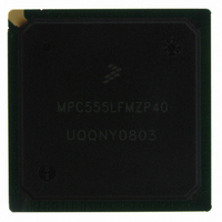
MPC555LFMZP40
Description
IC MCU 32BIT 40MHZ 272-BGA
Manufacturer
Freescale Semiconductor
Series
MPC5xxr
Datasheets
1.MPC555LFMZP40.pdf
(12 pages)
2.MPC555LFMZP40.pdf
(966 pages)
3.MPC555LFMZP40.pdf
(3 pages)
Specifications of MPC555LFMZP40
Core Processor
PowerPC
Core Size
32-Bit
Speed
40MHz
Connectivity
CAN, EBI/EMI, SCI, SPI, UART/USART
Peripherals
POR, PWM, WDT
Number Of I /o
101
Program Memory Size
448KB (448K x 8)
Program Memory Type
FLASH
Ram Size
26K x 8
Voltage - Supply (vcc/vdd)
2.5 V ~ 2.7 V
Data Converters
A/D 32x10b
Oscillator Type
External
Operating Temperature
-40°C ~ 125°C
Package / Case
272-PBGA
Controller Family/series
POWER 5xx
Ram Memory Size
26KB
Cpu Speed
63MIPS
Embedded Interface Type
QSPI, SCI, TouCAN
Operating Temperature Range
-40°C To +125°C
No. Of Pins
272
Rohs Compliant
No
Processor Series
MPC5xx
Core
PowerPC
Data Bus Width
32 bit
Data Ram Size
26 KB
Interface Type
CAN, QSPI, SCI
Maximum Clock Frequency
40 MHz
Number Of Programmable I/os
101
Operating Supply Voltage
3.3 V to 5 V
Maximum Operating Temperature
+ 125 C
Mounting Style
SMD/SMT
Development Tools By Supplier
MPC555CMEE
Minimum Operating Temperature
- 85 C
On-chip Adc
10 bit, 32 Channel
Cpu Family
MPC55xx
Device Core
PowerPC
Device Core Size
32b
Frequency (max)
40MHz
Total Internal Ram Size
32KB
# I/os (max)
101
Operating Supply Voltage (typ)
5V
Instruction Set Architecture
RISC
Operating Temp Range
-40C to 85C
Operating Temperature Classification
Industrial
Mounting
Surface Mount
Pin Count
272
Package Type
BGA
For Use With
MPC555CMEE - KIT EVAL FOR MPC555
Lead Free Status / RoHS Status
Contains lead / RoHS non-compliant
Eeprom Size
-
Lead Free Status / Rohs Status
No
Available stocks
Company
Part Number
Manufacturer
Quantity
Price
Company:

Part Number:
MPC555LFMZP40
Manufacturer:
MOTOLOLA
Quantity:
853
Company:
Part Number:
MPC555LFMZP40
Manufacturer:
Freescale Semiconductor
Quantity:
10 000
Company:
Part Number:
MPC555LFMZP40R2
Manufacturer:
Freescale Semiconductor
Quantity:
10 000


7.5.3 Soft Reset Configuration
MPC555
USER’S MANUAL
Bit(s)
13:14
17:18
24:27
28:30
NOTES:
11
12
15
16
19
20
21
22
23
31
1. This bit is available only on the MPC555 / MPC556.
When a soft reset event occurs, the MPC555 / MPC556 reconfigures the development
port. Refer to
Table 7-5 Hard Reset Configuration Word Bit Descriptions (Continued)
/
MPC556
COMP
COMP
ATWC
PRPM
Name
DBPC
EBDF
ETRE
EXC_
FLEN
DME
EN_
ISB
SC
—
—
—
1
1
SECTION 21 DEVELOPMENT SUPPORT
Debug port pins configuration. See
field definition. The default value is for these pins to function as development support pins.
Address type write-enable configuration. Refer to
ister
External bus division factor. This field defines the initial value of the external bus frequency.
Refer to
CLKOUT frequency is equal to that of the internal clock (divide by one).
Reserved
Peripheral mode enable. This bit determines whether the chip is in peripheral mode. Refer to
6.13.1.3 External Master Control Register (EMCR)
ripheral mode is not enabled.
Single chip select. Refer to
00 = Extended chip, 32 bits data
01 = Extended chip, 16 bits data
10 = Single chip and show cycles (address)
11 = Single chip
Exception table relocation enable. This field defines whether the exception table relocation
feature in the BBC is enabled or disabled. The default state is disabled. Refer to
BURST BUFFER
Flash Enable — This field determines whether the on-chip flash memory is enabled or dis-
abled out of reset. The default state is disabled, which means that by default, the boot is from
external memory.
0 = Flash disabled — boot is from external memory
1 = Flash enabled
Enable Compression — This bit enables the operation of the MPC555 / MPC556 with com-
pressed code. The default state is disabled. See
Exception Compression — This bit determines the operation of the MPC555 with exceptions.
If this bit is set, than the MPC555 assumes that ALL the exception routines are in compressed
code. The default indicates the exceptions are all non-compressed. See
This bit should not be high in the reset configuration word.
Reserved
Initial internal space base select. This field defines the initial value of the ISB field in the IMMR
register. Refer to
the internal memory map is mapped to start at address 0x0000 0000.
Dual mapping enable. This bit determines whether dual mapping of the flash EEPROM mod-
ule is enabled. Refer to
value is for dual mapping to be disabled.
0 = Dual mapping disabled
1 = Dual mapping enabled
for this field definition. The default value is for these pins to function as write-enable pins.
Freescale Semiconductor, Inc.
For More Information On This Product,
8.12.1 System Clock Control Register (SCCR)
6.13.1.2 Internal Memory Map Register
for details.
Go to: www.freescale.com
Rev. 15 October 2000
10.8.5 Dual Mapping Base Register (DMBR)
6.13.1.1 SIU Module Configuration Register
RESET
6.13.1.1 SIU Module Configuration Register
Description
Table
6.13.1.1 SIU Module Configuration Reg-
for details. The default value is that pe-
for details.
4-8.
for details. The default value is that
for details. The default state is that
for details.The default
Table
for details.
MOTOROLA
4-8.
SECTION 4
for this
7-13
Related parts for MPC555LFMZP40
Image
Part Number
Description
Manufacturer
Datasheet
Request
R

Part Number:
Description:
Manufacturer:
Freescale Semiconductor, Inc
Datasheet:
Part Number:
Description:
Manufacturer:
Freescale Semiconductor, Inc
Datasheet:
Part Number:
Description:
Manufacturer:
Freescale Semiconductor, Inc
Datasheet:
Part Number:
Description:
Manufacturer:
Freescale Semiconductor, Inc
Datasheet:
Part Number:
Description:
Manufacturer:
Freescale Semiconductor, Inc
Datasheet:
Part Number:
Description:
Manufacturer:
Freescale Semiconductor, Inc
Datasheet:
Part Number:
Description:
Manufacturer:
Freescale Semiconductor, Inc
Datasheet:
Part Number:
Description:
Manufacturer:
Freescale Semiconductor, Inc
Datasheet:
Part Number:
Description:
Manufacturer:
Freescale Semiconductor, Inc
Datasheet:
Part Number:
Description:
Manufacturer:
Freescale Semiconductor, Inc
Datasheet:
Part Number:
Description:
Manufacturer:
Freescale Semiconductor, Inc
Datasheet:
Part Number:
Description:
Manufacturer:
Freescale Semiconductor, Inc
Datasheet:
Part Number:
Description:
Manufacturer:
Freescale Semiconductor, Inc
Datasheet:
Part Number:
Description:
Manufacturer:
Freescale Semiconductor, Inc
Datasheet:
Part Number:
Description:
Manufacturer:
Freescale Semiconductor, Inc
Datasheet: