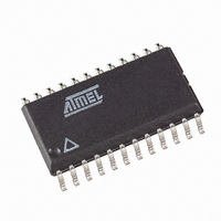
T89C51CC02CA-TDSIM Atmel, T89C51CC02CA-TDSIM Datasheet - Page 94

T89C51CC02CA-TDSIM
Manufacturer Part Number
T89C51CC02CA-TDSIM
Description
IC 8051 MCU FLASH 16K 24SOIC
Manufacturer
Atmel
Series
AT89C CANr
Datasheets
1.T89C51CC02CA-TDSIM.pdf
(159 pages)
2.T89C51CC02CA-TDSIM.pdf
(33 pages)
3.T89C51CC02CA-TDSIM.pdf
(29 pages)
4.T89C51CC02CA-TDSIM.pdf
(148 pages)
Specifications of T89C51CC02CA-TDSIM
Core Processor
8051
Core Size
8-Bit
Speed
40MHz
Connectivity
CAN, UART/USART
Peripherals
POR, PWM, WDT
Number Of I /o
20
Program Memory Size
16KB (16K x 8)
Program Memory Type
FLASH
Eeprom Size
2K x 8
Ram Size
512 x 8
Voltage - Supply (vcc/vdd)
3 V ~ 5.5 V
Data Converters
A/D 8x10b
Oscillator Type
External
Operating Temperature
-40°C ~ 85°C
Package / Case
24-SOIC (7.5mm Width)
For Use With
AT89STK-06 - KIT DEMOBOARD 8051 MCU W/CAN
Lead Free Status / RoHS Status
Contains lead / RoHS non-compliant
Other names
T89C51CC02CATDSIM
- T89C51CC02CA-TDSIM PDF datasheet
- T89C51CC02CA-TDSIM PDF datasheet #2
- T89C51CC02CA-TDSIM PDF datasheet #3
- T89C51CC02CA-TDSIM PDF datasheet #4
- Current page: 94 of 159
- Download datasheet (2Mb)
Registers
94
AT/T89C51CC02
Table 56. CANGCON Register
CANGCON (S:ABh)
CAN General Control Register
Reset Value = 0000 0000b
ABRQ
Bit Number
7
7
6
5
4
3
2
1
0
OVRQ
6
Bit Mnemonic
AUTOBAUD
SYNCTTC
ENA/STB
OVRQ
ABRQ
GRES
TEST
TTC
TTC
5
Description
Abort Request
Not an auto-resetable bit. A reset of the ENCH bit (message object
control & DLC register) is done for each message object. The
pending transmission communications are immediately aborted but
the on-going communication will be terminated normally, setting
the appropriate status flags, TxOk or RxOk.
Overload Frame Request (Initiator).
Auto-resetable bit.
Set to send an overload frame after the next received message.
Cleared by the hardware at the beginning of transmission of the
overload frame.
Network in Timer Trigger Communication
set to select node in TTC.
clear to disable TTC features.
Synchronization of TTC
When this bit is set the TTC timer is caught on the last bit of the
End Of Frame.
When this bit is clear the TTC timer is caught on the Start Of
Frame.
This bit is only used in the TTC mode.
AUTOBAUD
set to active listening mode.
Clear to disable listening mode
Test mode. The test mode is intended for factory testing and not for
customer use.
Enable/Standby CAN Controller
When this bit is set, it enables the CAN controller and its input
clock.
When this bit is clear, the on-going communication is terminated
normally and the CAN controller state of the machine is frozen (the
ENCH bit of each message object does not change).
In the standby mode, the transmitter constantly provides a
recessive level; the receiver is not activated and the input clock is
stopped in the CAN controller. During the disable mode, the
registers and the mailbox remain accessible.
Note that two clock periods are needed to start the CAN controller
state of the machine.
General Reset (Software Reset).
Auto-resetable bit. This reset command is ‘ORed’ with the
hardware reset in order to reset the controller. After a reset, the
controller is disabled.
SYNCTTC
4
AUTOBAUD
3
TEST
2
ENA
1
4126L–CAN–01/08
GRES
0
Related parts for T89C51CC02CA-TDSIM
Image
Part Number
Description
Manufacturer
Datasheet
Request
R

Part Number:
Description:
8-Bit MCU
Manufacturer:
Atmel
Datasheet:

Part Number:
Description:
DEV KIT FOR AVR/AVR32
Manufacturer:
Atmel
Datasheet:

Part Number:
Description:
INTERVAL AND WIPE/WASH WIPER CONTROL IC WITH DELAY
Manufacturer:
ATMEL Corporation
Datasheet:

Part Number:
Description:
Low-Voltage Voice-Switched IC for Hands-Free Operation
Manufacturer:
ATMEL Corporation
Datasheet:

Part Number:
Description:
MONOLITHIC INTEGRATED FEATUREPHONE CIRCUIT
Manufacturer:
ATMEL Corporation
Datasheet:

Part Number:
Description:
AM-FM Receiver IC U4255BM-M
Manufacturer:
ATMEL Corporation
Datasheet:

Part Number:
Description:
Monolithic Integrated Feature Phone Circuit
Manufacturer:
ATMEL Corporation
Datasheet:

Part Number:
Description:
Multistandard Video-IF and Quasi Parallel Sound Processing
Manufacturer:
ATMEL Corporation
Datasheet:

Part Number:
Description:
High-performance EE PLD
Manufacturer:
ATMEL Corporation
Datasheet:

Part Number:
Description:
8-bit Flash Microcontroller
Manufacturer:
ATMEL Corporation
Datasheet:

Part Number:
Description:
2-Wire Serial EEPROM
Manufacturer:
ATMEL Corporation
Datasheet:


