JBXFE2G12MSSDSR Souriau Connection Technology, JBXFE2G12MSSDSR Datasheet - Page 5
JBXFE2G12MSSDSR
Manufacturer Part Number
JBXFE2G12MSSDSR
Description
CONN PLUG 12POS SEAL IP67 SOLDER
Manufacturer
Souriau Connection Technology
Series
JBXr
Specifications of JBXFE2G12MSSDSR
Connector Type
Plug, Male Pins
Number Of Positions
12
Shell Size - Insert
2
Mounting Type
Free Hanging (In-Line)
Termination
Solder
Fastening Type
Push-Pull
Orientation
G
Ingress Protection
IP67 - Dust Tight, Waterproof
Shell Material, Finish
Brass, Chrome over Nickel
Features
Cable Clamp, Shielded
Product Type
Connectors
Shell Style
Plug
Number Of Contacts
12
Lead Free Status / RoHS Status
Lead free / RoHS Compliant
Shell Size, Military
-
Lead Free Status / Rohs Status
Lead free / RoHS Compliant
Other names
SOU1617


REV 4 – April 14, 2004
6. Removal of contacts:
7. Take the keyed half bushing (#6) and place it over the insulator so that the window is lined up
8. Take the collet that is pre-loaded on the cable and align the slots in the collet with the keys on
9. Take a connector housing (#7) and slide it over the insulator so that the red dot on the
10. Once the assembly is installed into the connector housing and is aligned properly, apply thread
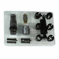
TOOLINGS – JBX – JKX
Manual Extraction Tools
with the key on the insulator and the key on the half bushing is pointing to the back of the
insulator (position loading path indicator (worm end)). Then take the half bushing without the
window (#6) and place on the opposite side of the insulator so that both half bushings are
aligned with each other.
the end of the half bushings (you may need to move the braid away from the slots and spin the
collet slightly). Once they are aligned, compress the assembly so that it is in line and there are
no gaps between the collet & the half bushings. The braid should still be in place once the
assembly is inserted.
connector housing lines up with the key on the half bushing with window. Push the whole
assembly into the connector housing until it bottoms out. Insure that the keys are seated
properly by turning the collet that is already aligned with the half bushings. If the collet does
not turn, then the keys are correctly aligned. If the collet does turn, then you must withdraw the
assembly & realign the keys.
lock to thread area. Then slide the back nut up until you can manually start the back nut threads
onto the threaded end of the connector housing. Tighten the back nut up as far as you can by
hand, then take the appropriate wrenches and place the wrenches onto the flats located on the
connector housing. Do not over torque back nut as it can cause connector failure.
a. Using the proper extraction tool insert the tool over the front of the contact and push
contact out. Failure to use the proper extraction tool can result in damage to the contact.
Contacts automatically extracted without pulling on the cable.
The extraction tool is the same for both male and female contacts.
Related parts for JBXFE2G12MSSDSR
Image
Part Number
Description
Manufacturer
Datasheet
Request
R

Part Number:
Description:
CONN SEALING FOR WALL RCPT #22
Manufacturer:
Souriau Connection Technology
Part Number:
Description:
CONN SEALING FOR WALL RCPT #14
Manufacturer:
Souriau Connection Technology
Datasheet:

Part Number:
Description:
CONN RCPT SEALING CAP SIZE 10
Manufacturer:
Souriau Connection Technology
Datasheet:

Part Number:
Description:
CONN RCPT SEALING CAP SIZE 14
Manufacturer:
Souriau Connection Technology
Datasheet:

Part Number:
Description:
CONN STRAIN RELIEF 12POS
Manufacturer:
Souriau Connection Technology
Datasheet:

Part Number:
Description:
D38999 Series 3
Manufacturer:
Souriau Connection Technology
Datasheet: