SY89250VMI TR Micrel Inc, SY89250VMI TR Datasheet - Page 4
SY89250VMI TR
Manufacturer Part Number
SY89250VMI TR
Description
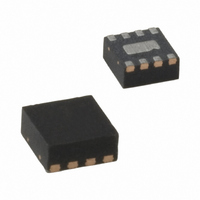
IC RECEIVER DIFF 3.3V/5V 8-MLF
Manufacturer
Micrel Inc
Series
SY89r
Datasheet
1.SY89250VMG_TR.pdf
(6 pages)
Specifications of SY89250VMI TR
Logic Type
Differential Receiver
Supply Voltage
3.3V, 5V
Operating Temperature
-40°C ~ 85°C
Mounting Type
Surface Mount
Package / Case
8-MLF®, QFN
Lead Free Status / RoHS Status
Contains lead / RoHS non-compliant
Number Of Bits
-
Other names
SY89250VMITR
SY89250VMITR
SY89250VMITR


Micrel, Inc.
V
Symbol
t
t
t
t
V
V
t
Notes:
5. Duty cycle skew is the difference between a t
6. Minimum input swing for which AC parameters are guaranteed. The device has a DC gain of
7. The CMR range is referenced to the most positive side of the differential input signal. Normal operation is obtained if the HIGH level falls within the
M9999-052505
hbwhelp@micrel.com or (408) 955-1690
pd
S
H
SKEW
r
, t
EE
PP
CMR
AC ELECTRICAL CHARACTERISTICS
TIMING DIAGRAM
to /Q
specified range and the peak-to-peak voltage lies between V
the spec table assume a nominal V
f
= V
HG
EE
, Q
(min) to V
HG
Q
/EN
HG
Parameter
Propagation Delay to:
Q, /Q Output
QHG, /QHG Output
Set-Up Time
Hold Time
Duty Cycle Skew
Minimum Input Swing
Common Mode Range
Output Q Rise/Fall Times
(20% to 80%)
outputs.
D
Q
EE
(max); V
CC
EE
= GND; T
= –3.3V. Note for PECL operation, the V
pd
A
D (Diff)
D (Diff)
D (SE)
D (SE)
propagation delay through a device.
= –40 C to +85 C; unless otherwise stated.
(Diff)
/EN
/EN
/EN
/EN
Condition
Note 5
Note 6
Note 7
At full output swing
PP
(min) and 1V. The lower end of the CMR range varies 1:1 with V
t
S
4
CMR
(min) will be fixed at 3.3V – |V
t
H
40 to Q, /Q outputs and a DC gain of
–1.3
Min
150
100
CMR
(min)|.
Typ
150
150
225
5
EE
Precision Edge
. The numbers in
Max
–0.4
380
430
730
780
350
20
200 or higher
SY89250V
Units
mV
ps
ps
ps
ps
ps
ps
ps
ps
V
®
Related parts for SY89250VMI TR
Image
Part Number
Description
Manufacturer
Datasheet
Request
R

Part Number:
Description:
Manufacturer:
Micrel Inc
Datasheet:
Part Number:
Description:
Manufacturer:
Micrel Inc
Datasheet:
Part Number:
Description:
Manufacturer:
Micrel Inc
Datasheet:
Part Number:
Description:
Manufacturer:
Micrel Inc
Datasheet:
Part Number:
Description:
Manufacturer:
Micrel Inc
Datasheet:
Part Number:
Description:
Manufacturer:
Micrel Inc
Datasheet:
Part Number:
Description:
Manufacturer:
Micrel Inc
Datasheet:
Part Number:
Description:
Manufacturer:
Micrel Inc
Datasheet:
Part Number:
Description:
Manufacturer:
Micrel Inc
Datasheet:
Part Number:
Description:
Manufacturer:
Micrel Inc
Datasheet:
Part Number:
Description:
Manufacturer:
Micrel Inc
Datasheet:
Part Number:
Description:
Manufacturer:
Micrel Inc
Datasheet:
Part Number:
Description:
Manufacturer:
Micrel Inc
Datasheet:
Part Number:
Description:
Manufacturer:
Micrel Inc
Datasheet: