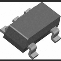
LM397MF/NOPB National Semiconductor, LM397MF/NOPB Datasheet - Page 4

LM397MF/NOPB
Manufacturer Part Number
LM397MF/NOPB
Description
IC COMPARATOR VOLT SGL SOT23-5
Manufacturer
National Semiconductor
Datasheet
1.LM397MFNOPB.pdf
(8 pages)
Specifications of LM397MF/NOPB
Comparator Type
General Purpose
No. Of Comparators
1
Response Time
250ns
Ic Output Type
CMOS, TTL, Open-Collector
Supply Current
300µA
Supply Voltage Range
5V To 30V
Rohs Compliant
Yes
Output Compatibility
CMOS, TTL
Lead Free Status / RoHS Status
Lead free / RoHS Compliant
Other names
*LM397MF::*LM397MF/NOPB::LM397MF
www.national.com
Application Notes
Basic Comparators
A comparator is quite often used to convert an analog signal
to a digital signal. The comparator compares an input volt-
age (V
(V
(V
output voltage (V
Hysteresis
The basic comparator configuration may oscillate or produce
a noisy output if the applied differential input is near the
comparator’s input offset voltage. This tends to occur when
the voltage on the input is equal or very close to the other
input voltage. Adding hysteresis can prevent this problem.
Hysteresis creates two switching thresholds (one for the
rising input voltage and the other for the falling input volt-
age). Hysteresis is the voltage difference between the two
switching thresholds. When both inputs are nearly equal,
hysteresis causes one input to effectively move quickly pass
the other. Thus, effectively moving the input out of region that
oscillation may occur.
For an inverting configured comparator, hysteresis can be
added with a three resistor network and positive feedback.
REF
O
) is low (V
) at the inverting pin. If V
IN
) at the non-inverting pin to the reference voltage
OL
FIGURE 2. Basic Comparator
). However, if V
O
) is high (V
OH
IN
IN
is less than V
). Refer to Figure 2.
is greater than V
20022110
REF
the output
20022111
REF
, the
4
When input voltage (V
non-inverting node (V
circuit for the three resistor network is R
and in series with R
calculated by:
When V
equivalent circuit for the three resistor network is R
parallel with R
voltage V
The hysteresis is defined as
FIGURE 3. Inverting Configured Comparator – LM397
V
T2
= V
V
IN
T1
T2
is greater than V
S
= ((V
is calculated by:
((R
3
2
and in series with R
S
R
R
3
) / (R
2
∆V
2
) / (((R
T
. The lower threshold voltage V
IN
), the output is high. The equivalent
IN
) at the inverting node is less than
2
= V
+ R
R
T
1
, the output voltage is low. The
3
R
)))
T1
3
3
)) / (R
) / (R
– V
1
T2
1
1
. The upper threshold
+ ((R
+ R
1
in parallel with R
3
)) + R
2
R
20022113
3
20022112
) / (R
2
))
2
T1
2
+
in
is
3


