STM32F405RGT6 STMicroelectronics, STM32F405RGT6 Datasheet - Page 124
STM32F405RGT6
Manufacturer Part Number
STM32F405RGT6
Description
Microcontrollers (MCU) ARM M4 1024 FLASH 168 Mhz 192kB SRAM
Manufacturer
STMicroelectronics
Datasheet
1.STM32F407ZGT6.pdf
(167 pages)
Specifications of STM32F405RGT6
Core
ARM Cortex M4
Processor Series
STM32F4
Data Bus Width
32 bit
Maximum Clock Frequency
168 MHz
Program Memory Size
1024 KB
Data Ram Size
192 KB
On-chip Adc
Yes
Number Of Programmable I/os
51
Number Of Timers
10
Operating Supply Voltage
1.7 V to 3.6 V
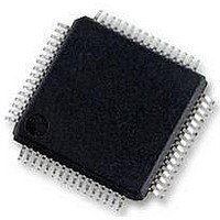
Package / Case
LQFP-64
Mounting Style
SMD/SMT
A/d Bit Size
12 bit
A/d Channels Available
16
Interface Type
CAN, I2C, I2S, SPI, UART
Program Memory Type
Flash
Lead Free Status / Rohs Status
Details
Available stocks
Company
Part Number
Manufacturer
Quantity
Price
Company:

Part Number:
STM32F405RGT6
Manufacturer:
ON
Quantity:
1 001
Company:
Part Number:
STM32F405RGT6
Manufacturer:
STMicroelectronics
Quantity:
10 000
Part Number:
STM32F405RGT6
Manufacturer:
ST
Quantity:
20 000


Electrical characteristics
5.3.24
Table 70.
124/167
V
V
V
R
R
C
DAC_OUT
min
DAC_OUT
max
DAC_OUT
min
DAC_OUT
max
I
I
DNL
VREF+
DDA
DDA
REF+
SSA
O
LOAD
LOAD
Symbol
(2)
(2)
(2)
(2)
(2)
(3)
(3)
(2)
(2)
(3)
Analog supply voltage
Reference supply voltage
Ground
Resistive load with buffer ON
Impedance output with buffer
OFF
Capacitive load
Lower DAC_OUT voltage
with buffer ON
Higher DAC_OUT voltage
with buffer ON
Lower DAC_OUT voltage
with buffer OFF
Higher DAC_OUT voltage
with buffer OFF
DAC DC V
consumption in quiescent
mode (Standby mode)
DAC DC VDDA current
consumption in quiescent
mode (Standby mode)
Differential non linearity
Difference between two
consecutive code-1LSB)
DAC electrical characteristics
DAC characteristics
Parameter
REF
current
1.8
1.8
Min
0.2
0
5
-
-
-
-
-
-
-
-
-
-
-
Doc ID 022152 Rev 2
(1)
(1)
Typ
170
280
475
0.5
50
-
-
-
-
-
-
-
-
-
-
-
V
REF+
V
DDA
Max
±0.5
240
380
625
3.6
3.6
±2
15
50
75
0
-
-
-
– 1LSB
– 0.2
Unit
LSB
LSB
mV
kΩ
kΩ
µA
µA
µA
pF
V
V
V
V
V
V
V
When the buffer is OFF, the
Minimum resistive load between
DAC_OUT and V
accuracy is 1.5 MΩ
Maximum capacitive load at
DAC_OUT pin (when the buffer is
ON).
It gives the maximum output
excursion of the DAC.
It corresponds to 12-bit input code
(0x0E0) to (0xF1C) at V
3.6 V and (0x1C7) to (0xE38) at
V
It gives the maximum output
excursion of the DAC.
With no load, worst code (0x800)
at V
consumption on the inputs
With no load, worst code (0xF1C)
at V
consumption on the inputs
With no load, middle code (0x800)
on the inputs
With no load, worst code (0xF1C)
at V
consumption on the inputs
Given for the DAC in 10-bit
configuration.
Given for the DAC in 12-bit
configuration.
STM32F405xx, STM32F407xx
REF+
REF+
REF+
REF+
REF+
≤ V
= 1.8 V
= 3.6 V in terms of DC
= 3.6 V in terms of DC
= 3.6 V in terms of DC
DDA
Comments
SS
to have a 1%
REF+
=
Related parts for STM32F405RGT6
Image
Part Number
Description
Manufacturer
Datasheet
Request
R

Part Number:
Description:
Microsoft .NET Micro Framework environment for STM32F4 microcontrollers
Manufacturer:
STMICROELECTRONICS [STMicroelectronics]
Datasheet:

Part Number:
Description:
DEV KIT FOR STM32
Manufacturer:
STMicroelectronics
Datasheet:

Part Number:
Description:
MCU ARM 128KB FLASH MEM 64-LQFP
Manufacturer:
STMicroelectronics
Datasheet:

Part Number:
Description:
MCU ARM 32BIT 128KB FLASH 64BGA
Manufacturer:
STMicroelectronics
Datasheet:

Part Number:
Description:
MCU ARM 32BIT 256K FLASH 144LQFP
Manufacturer:
STMicroelectronics
Datasheet:

Part Number:
Description:
KIT STARTER FOR STM32F10X
Manufacturer:
STMicroelectronics
Datasheet:

Part Number:
Description:
MCU ARM 128K FLASH/TIMER
Manufacturer:
STMicroelectronics
Datasheet:

Part Number:
Description:
MCU ARM 128KB FLASH MEM 100-LQFP
Manufacturer:
STMicroelectronics
Datasheet:

Part Number:
Description:
MCU 32BIT ARM 64K FLASH 36VFQFPN
Manufacturer:
STMicroelectronics
Datasheet:
Part Number:
Description:
MCU ARM 32BIT 32KB FLASH 48LQFP
Manufacturer:
STMicroelectronics
Datasheet:
Part Number:
Description:
MCU ARM 32BIT 64KB FLASH 64LQFP
Manufacturer:
STMicroelectronics
Datasheet:
Part Number:
Description:
MCU ARM 32BIT 384KB FLASH 64LQFP
Manufacturer:
STMicroelectronics
Datasheet:

Part Number:
Description:
MCU 32BIT ARM 512K FLASH 100-LQF
Manufacturer:
STMicroelectronics
Datasheet:
Part Number:
Description:
MCU ARM 32BIT 512KB FLASH 144BGA
Manufacturer:
STMicroelectronics
Datasheet:
Part Number:
Description:
MCU ARM 32BIT 512K FLASH 144LQFP
Manufacturer:
STMicroelectronics
Datasheet: