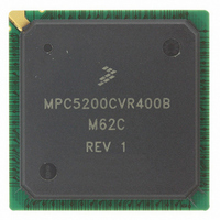
MPC5200CVR400B Freescale Semiconductor, MPC5200CVR400B Datasheet - Page 24

MPC5200CVR400B
Manufacturer Part Number
MPC5200CVR400B
Description
IC MPU 32BIT 400MHZ 272-PBGA
Manufacturer
Freescale Semiconductor
Specifications of MPC5200CVR400B
Processor Type
MPC52xx PowerPC 32-Bit
Speed
400MHz
Voltage
1.5V
Mounting Type
Surface Mount
Package / Case
272-PBGA
Processor Series
MPC52xx
Core
e300
Development Tools By Supplier
MEDIA5200KIT1E
Maximum Clock Frequency
400 MHz
Maximum Operating Temperature
+ 105 C
Mounting Style
SMD/SMT
I/o Voltage
2.5 V, 3.3 V
Minimum Operating Temperature
- 40 C
Core Size
32 Bit
No. Of I/o's
56
Ram Memory Size
16KB
Cpu Speed
400MHz
No. Of Timers
8
Embedded Interface Type
CAN, I2C, SCI, SPI
No. Of Pwm Channels
8
Digital Ic Case Style
TEPBGA
Rohs Compliant
Yes
Lead Free Status / RoHS Status
Lead free / RoHS Compliant
Features
-
Lead Free Status / Rohs Status
Lead free / RoHS Compliant
Available stocks
Company
Part Number
Manufacturer
Quantity
Price
Company:
Part Number:
MPC5200CVR400B
Manufacturer:
Marvell
Quantity:
1 001
Company:
Part Number:
MPC5200CVR400B
Manufacturer:
FREESCAL
Quantity:
200
Company:
Part Number:
MPC5200CVR400B
Manufacturer:
Freescale Semiconductor
Quantity:
10 000
Part Number:
MPC5200CVR400B
Manufacturer:
FREESCALE
Quantity:
20 000
Company:
Part Number:
MPC5200CVR400BM62C
Manufacturer:
FRRESCAL..
Quantity:
2 831
Electrical and Thermal Characteristics
The position of the t
signal indicate if the read data are valid. If the controller is not able to detect a valid MDQS signal on the
sample time (sample position A) then the controller will look for valid MDQS / data on the next edge of
the MEM_CLK signal (sample position B). Depend on the board travel time, different working tap delay
configurations are possible. For a fast connection the data will be sampled with the next edge of
MEM_CLK, this shows
positions are possible.
bigger board delay only sample position B will be possible.
The equation below shows how to calculate the upper and lower limit. The right Tap delay number is
selected, when the possible max and min sample timing is within the memory data valid window.
24
•
•
t
t
t
t
data_sample_max
data_sample_min
data_sample_min
data_sample_min
t
data_valid_max
t
data_valid_min
delay [ns]
4.59
1.55
8.34
Figure 8. Read Data sample window depend on the number of Tap delay
0
data_valid
Figure 8
= min((1.55 + TapNum * 0.095), (1.74 + TapNum * 0.045))
= max((1.55 + TapNum * 0.095), (1.74 + TapNum * 0.045))
Figure
window is depend on the clock / data flight time on the board. The MDQS
8, sample position A. With a longer connection maybe two sample
shows a example with two working sample position (A and B). With a
Working Tap Delay range
for sample position B
MPC5200 Data Sheet, Rev. 4
Memory Data valid window
Working Tap Delay range
for sample position A
selected Tap delay
Possible sample
time over PVT for one
selected Tap delay
Freescale Semiconductor
31
Tap delay number


