MPC5200CVR400B Freescale Semiconductor, MPC5200CVR400B Datasheet - Page 19
MPC5200CVR400B
Manufacturer Part Number
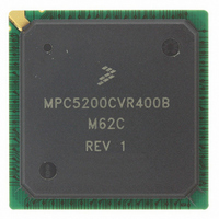
MPC5200CVR400B
Description
IC MPU 32BIT 400MHZ 272-PBGA
Manufacturer
Freescale Semiconductor
Specifications of MPC5200CVR400B
Processor Type
MPC52xx PowerPC 32-Bit
Speed
400MHz
Voltage
1.5V
Mounting Type
Surface Mount
Package / Case
272-PBGA
Processor Series
MPC52xx
Core
e300
Development Tools By Supplier
MEDIA5200KIT1E
Maximum Clock Frequency
400 MHz
Maximum Operating Temperature
+ 105 C
Mounting Style
SMD/SMT
I/o Voltage
2.5 V, 3.3 V
Minimum Operating Temperature
- 40 C
Core Size
32 Bit
No. Of I/o's
56
Ram Memory Size
16KB
Cpu Speed
400MHz
No. Of Timers
8
Embedded Interface Type
CAN, I2C, SCI, SPI
No. Of Pwm Channels
8
Digital Ic Case Style
TEPBGA
Rohs Compliant
Yes
Lead Free Status / RoHS Status
Lead free / RoHS Compliant
Features
-
Lead Free Status / Rohs Status
Lead free / RoHS Compliant
Available stocks
Company
Part Number
Manufacturer
Quantity
Price
Company:

Part Number:
MPC5200CVR400B
Manufacturer:
Marvell
Quantity:
1 001
Company:
Part Number:
MPC5200CVR400B
Manufacturer:
FREESCAL
Quantity:
200
Company:
Part Number:
MPC5200CVR400B
Manufacturer:
Freescale Semiconductor
Quantity:
10 000
Part Number:
MPC5200CVR400B
Manufacturer:
FREESCALE
Quantity:
20 000
Company:
Part Number:
MPC5200CVR400BM62C
Manufacturer:
FRRESCAL..
Quantity:
2 831


Notes:
1) The frequency of IP_CLK depends on register settings in Clock Distribution Module. See the MPC5200 User Manual [1].
2) The interrupt latency descriptions in the table above are related to non competitive, non masked but enabled external
Since all external interrupt signals are synchronized into the internal processor bus clock domain, each of
these signals has to exceed a minimum pulse width of more than one IP_CLK cycle.
NOTES:
1) The frequency of the IP_CLK depends on the register settings in Clock Distribution Module. See the MPC5200 User Manual
2) If the same interrupt occurs a second time while its interrupt service routine has not cleared the former one, the second
Besides synchronization, prioritization, and mapping the latency of an external interrupt to the start of its
associated interrupt service routine also depends on the following conditions: To get a minimum interrupt
service response time, it is recommended to enable the instruction cache and set up the maximum core
clock, XL bus, and IP bus frequencies (depending on board design and programming). In addition, it is
advisable to execute an interrupt handler, which has been implemented in assembly code.
Freescale Semiconductor
All external interrupts (IRQs, GPIOs)
interrupt sources. Take care of interrupt prioritization which may increase the latencies.
[1] for further information.
interrupt will not be recognized at all.
Standard GPIO Interrupts
GPIO WakeUp Interrupts
Interrupt Type
Table 17. Minimum pulse width for external interrupts to be recognized
Name
Table 16. External interrupt latencies (continued)
GPIO_PSC3_8
GPIO_PSC2_4
GPIO_PSC3_9
GPIO_ETHI_4
GPIO_ETHI_5
GPIO_ETHI_6
GPIO_ETHI_8
GPIO_IRDA_0
GPIO_USB_9
GPIO_
GPIO_
GPIO_PSC3_4
GPIO_PSC3_5
Pin Name
DGP_IN0
DGP_IN1
PSC1_4
ETHI_7
MPC5200 Data Sheet, Rev. 4
Min Pulse Width
> 1 clock cycle
Clock Cycles
12
12
12
12
12
12
12
12
12
12
12
12
12
12
12
Reference Clock
Max Pulse Width
IP_CLK
IP_CLK
IP_CLK
IP_CLK
IP_CLK
IP_CLK
IP_CLK
IP_CLK
IP_CLK
IP_CLK
IP_CLK
IP_CLK
IP_CLK
IP_CLK
IP_CLK
—
Electrical and Thermal Characteristics
Core Interrupt
Reference Clock
normal (int)
normal (int)
normal (int)
normal (int)
normal (int)
normal (int)
normal (int)
normal (int)
normal (int)
normal (int)
normal (int)
normal (int)
normal (int)
normal (int)
normal (int)
IP_CLK
SpecID
A4.10
A4.11
A4.12
A4.13
A4.14
A4.15
A4.16
A4.17
A4.18
A4.19
A4.20
A4.21
A4.7
A4.8
A4.9
SpecID
A4.22
19
Related parts for MPC5200CVR400B
Image
Part Number
Description
Manufacturer
Datasheet
Request
R

Part Number:
Description:
Manufacturer:
Freescale Semiconductor, Inc
Datasheet:
Part Number:
Description:
Manufacturer:
Freescale Semiconductor, Inc
Datasheet:
Part Number:
Description:
Manufacturer:
Freescale Semiconductor, Inc
Datasheet:
Part Number:
Description:
Manufacturer:
Freescale Semiconductor, Inc
Datasheet:
Part Number:
Description:
Manufacturer:
Freescale Semiconductor, Inc
Datasheet:
Part Number:
Description:
Manufacturer:
Freescale Semiconductor, Inc
Datasheet:
Part Number:
Description:
Manufacturer:
Freescale Semiconductor, Inc
Datasheet:
Part Number:
Description:
Manufacturer:
Freescale Semiconductor, Inc
Datasheet:
Part Number:
Description:
Manufacturer:
Freescale Semiconductor, Inc
Datasheet:
Part Number:
Description:
Manufacturer:
Freescale Semiconductor, Inc
Datasheet:
Part Number:
Description:
Manufacturer:
Freescale Semiconductor, Inc
Datasheet:
Part Number:
Description:
Manufacturer:
Freescale Semiconductor, Inc
Datasheet:
Part Number:
Description:
Manufacturer:
Freescale Semiconductor, Inc
Datasheet:
Part Number:
Description:
Manufacturer:
Freescale Semiconductor, Inc
Datasheet:
Part Number:
Description:
Manufacturer:
Freescale Semiconductor, Inc
Datasheet: