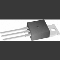
LM1084IS-ADJ National Semiconductor, LM1084IS-ADJ Datasheet - Page 8

LM1084IS-ADJ
Manufacturer Part Number
LM1084IS-ADJ
Description
Linear Voltage Regulator IC
Manufacturer
National Semiconductor
Datasheet
1.LM1084IS-ADJ.pdf
(13 pages)
Specifications of LM1084IS-ADJ
No. Of Pins
3
Output Current
1.5A
Termination Type
Through Hole
Mounting Type
Through Hole
Output Voltage Min
1.25V
Voltage Regulator Type
LDO Linear
Peak Reflow Compatible (260 C)
No
Lead Free Status / RoHS Status
Contains lead / RoHS non-compliant
Available stocks
Company
Part Number
Manufacturer
Quantity
Price
Part Number:
LM1084IS-ADJ
Manufacturer:
NS/国半
Quantity:
20 000
Company:
Part Number:
LM1084IS-ADJ
Manufacturer:
NSTI
Quantity:
5 823
Part Number:
LM1084IS-ADJ/NOPB
Manufacturer:
TI/德州仪器
Quantity:
20 000
www.national.com
Application Note
Figure 3 shows a typical application using a fixed output
regulator. Rt1 and Rt2 are the line resistances. V
than the V
resistances. In this case, the load regulation seen at the
R
To improve this, the load should be tied directly to the output
terminal on the positive side and directly tied to the ground
terminal on the negative side.
When the adjustable regulator is used (Figure 4), the best
performance is obtained with the positive side of the resistor
R1 tied directly to the output terminal of the regulator rather
than near the load. This eliminates line drops from appearing
effectively in series with the reference and degrading regu-
lation. For example, a 5V regulator with 0.05Ω resistance
between the regulator and load will have a load regulation
due to line resistance of 0.05Ω x I
nected near the load the effective line resistance will be
0.05Ω (1 + R2/R1) or in this case, it is 4 times worse. In
addition, the ground side of the resistor R2 can be returned
near the ground of the load to provide remote ground sens-
ing and improve load regulation.
PROTECTION DIODES
Under normal operation, the LM1084 regulator does not
need any protection diode. With the adjustable device, the
internal resistance between the adjustment and output ter-
minals limits the current. No diode is needed to divert the
current around the regulator even with a capacitor on the
LOAD
FIGURE 4. Best Load Regulation using Adjustable
FIGURE 3. Typical Application using Fixed Output
would be degraded from the data sheet specification.
OUT
by the sum of the voltage drops along the line
Output Regulator
Regulator
(Continued)
L
. If R1 (=125Ω) is con-
LOAD
10094618
10094619
is less
8
adjustment terminal. The adjust pin can take a transient
signal of
damaging the device.
When an output capacitor is connected to a regulator and
the input is shorted, the output capacitor will discharge into
the output of the regulator. The discharge current depends
on the value of the capacitor, the output voltage of the
regulator, and rate of decrease of V
lator, the internal diode between the output and input pins
can withstand microsecond surge currents of 10A to 20A.
With an extremely large output capacitor (≥1000 µf), and
with input instantaneously shorted to ground, the regulator
could be damaged. In this case, an external diode is recom-
mended between the output and input pins to protect the
regulator, shown in Figure 5.
OVERLOAD RECOVERY
Overload recovery refers to regulator’s ability to recover from
a short circuited output. A key factor in the recovery process
is the current limiting used to protect the output from drawing
too much power. The current limiting circuit reduces the
output current as the input to output differential increases.
Refer to short circuit curve in the curve section.
During normal start-up, the input to output differential is
small since the output follows the input. But, if the output is
shorted, then the recovery involves a large input to output
differential. Sometimes during this condition the current lim-
iting circuit is slow in recovering. If the limited current is too
low to develop a voltage at the output, the voltage will
stabilize at a lower level. Under these conditions it may be
necessary to recycle the power of the regulator in order to
get the smaller differential voltage and thus adequate start
up conditions. Refer to curve section for the short circuit
current vs. input differential voltage.
THERMAL CONSIDERATIONS
ICs heats up when in operation, and power consumption is
one factor in how hot it gets. The other factor is how well the
heat is dissipated. Heat dissipation is predictable by knowing
the thermal resistance between the IC and ambient (θ
Thermal resistance has units of temperature per power (C/
W). The higher the thermal resistance, the hotter the IC.
The LM1084 specifies the thermal resistance for each pack-
age as junction to case (θ
resistance to ambient (θ
FIGURE 5. Regulator with Protection Diode
±
25V with respect to the output voltage without
JA
), two other thermal resistance
JC
). In order to get the total
IN
. In the LM1084 regu-
10094615
JA
).


