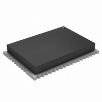
ATZB-24-A2 Atmel, ATZB-24-A2 Datasheet - Page 65

ATZB-24-A2
Manufacturer Part Number
ATZB-24-A2
Description
KIT MOD 802.15.4/ZIGB 2.4GHZ ANT
Manufacturer
Atmel
Specifications of ATZB-24-A2
Frequency
2.4GHz
Data Rate - Maximum
250kbps
Modulation Or Protocol
802.15.4 Zigbee
Applications
Home/Building Automation, Industrial Control and Monitoring
Power - Output
3dBm
Sensitivity
-101dBm
Voltage - Supply
1.8 V ~ 3.6 V
Current - Receiving
19mA
Current - Transmitting
18mA
Data Interface
PCB, Surface Mount
Memory Size
128kBytes Flash, 8kBytes RAM, 4kBytes EEPROM
Antenna Connector
On-Board, Chip
Operating Temperature
-40°C ~ 85°C
Package / Case
Module
Tool Type
Wireless Development Kit
Core Architecture
AVR
Cpu Core
AVR 8
Data Bus Width
8 bit
Description/function
ZigBit 2.4 GHz Dual Chip Antenna
Wireless Frequency
2.4 GHz
Interface Type
UART, I2C, SPI
Operating Voltage
1.8 V to 3.6 V
Output Power
3 dBm
Antenna
Chip Antenna
Operating Temperature Range
- 40 C to + 85 C
Lead Free Status / RoHS Status
Lead free / RoHS Compliant
Available stocks
Company
Part Number
Manufacturer
Quantity
Price
Part Number:
ATZB-24-A2
Manufacturer:
ATMEL/爱特梅尔
Quantity:
20 000
Company:
Part Number:
ATZB-24-A2R
Manufacturer:
CIRRUS
Quantity:
201
34.5
Table 34-5.
Note:
Table 34-6.
8069Q–AVR–12/10
Vrms
SCALEDVCC
INTVCC
Symbol
Symbol
ADC
AVCC
INT1V
VREF
R
RES
DNL
INL
AREF
clk
ADC Characteristics
1. Refer to
Parameter
Resolution
Integral Non-Linearity
Differential Non-Linearity
Gain Error
Offset Error
ADC Clock frequency
Conversion rate
Conversion time
(propagation delay)
Sampling Time
Conversion range
Analog Supply Voltage
Reference voltage
Input bandwidth
Internal 1.00V reference
Internal V
Scaled internal V
Reference input resistance
Start-up time
Internal input sampling speed
Parameter
Gain error
Offset error
Noise level at input
Clock rate
ADC Characteristics
ADC Gain Stage Characteristics
”Bandgap Characteristics” on page 66
CC
/1.6
CC
/10 input
(1)
1 to 64 gain
64x gain
Same as ADC
Programmable: 8/12
500 ksps
500 ksps
(RES+2)/2+GAIN
RES = 8 or 12, GAIN = 0 or 1
1/2 ADC
Temp. sensor, V
Max is 1/4 of Peripheral Clock
clk
for more parameter details.
Condition
Condition
cycle
CC
VREF = Int. 1V
VREF = Ext. 2V
/10, Bandgap
V
0.25
cc
Min
1.0
-5
8
5
0
-0.3
Min
V
V
< ±10
< ±1
< ±2
1.00
CC
> 10
Typ
CC
±2
12
12
7
/1.6
/10
< ±1
< ±1
0.12
0.06
Typ
XMEGA A4
V
V
VREF
cc
2000
2000
cc
Max
100
12
24
-0.6V
5
8
+0.3
1000
Max
ADC
ADC
cycles
cycles
Units
ksps
ksps
LSB
kHz
Bits
kHz
MΩ
mV
Units
uS
V
V
kHz
mV
%
clk
clk
65


