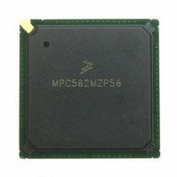
MPC562MZP56 Freescale Semiconductor, MPC562MZP56 Datasheet - Page 79

MPC562MZP56
Manufacturer Part Number
MPC562MZP56
Description
IC MPU 32BIT 56MHZ PPC 388-PBGA
Manufacturer
Freescale Semiconductor
Series
MPC5xxr
Datasheet
1.MPC561MZP56.pdf
(1420 pages)
Specifications of MPC562MZP56
Core Processor
PowerPC
Core Size
32-Bit
Speed
56MHz
Connectivity
CAN, EBI/EMI, SCI, SPI, UART/USART
Peripherals
POR, PWM, WDT
Number Of I /o
64
Program Memory Type
ROMless
Ram Size
32K x 8
Voltage - Supply (vcc/vdd)
2.5 V ~ 2.7 V
Data Converters
A/D 32x10b
Oscillator Type
External
Operating Temperature
-40°C ~ 125°C
Package / Case
388-BGA
Processor Series
MPC5xx
Core
PowerPC
Data Bus Width
32 bit
Data Ram Size
8 KB
Interface Type
SCI, SPI, UART
Maximum Clock Frequency
40 MHz
Number Of Programmable I/os
56
Number Of Timers
22
Operating Supply Voltage
2.6 V to 5 V
Maximum Operating Temperature
+ 85 C
Mounting Style
SMD/SMT
Minimum Operating Temperature
- 40 C
On-chip Adc
2 (10 bit, 32 Channel)
For Use With
MPC564EVB - KIT EVAL FOR MPC561/562/563/564
Lead Free Status / RoHS Status
Request inventory verification / Request inventory verification
Eeprom Size
-
Program Memory Size
-
Lead Free Status / Rohs Status
No
Available stocks
Company
Part Number
Manufacturer
Quantity
Price
Company:
Part Number:
MPC562MZP56
Manufacturer:
FREESCAL
Quantity:
204
Company:
Part Number:
MPC562MZP56
Manufacturer:
Freescale Semiconductor
Quantity:
10 000
Part Number:
MPC562MZP56
Manufacturer:
FREESCALE
Quantity:
20 000
Company:
Part Number:
MPC562MZP56R2
Manufacturer:
RFT
Quantity:
1 441
Company:
Part Number:
MPC562MZP56R2
Manufacturer:
Freescale Semiconductor
Quantity:
10 000
- Current page: 79 of 1420
- Download datasheet (11Mb)
This document also includes a register index and comprehensive index.
Freescale Semiconductor
•
•
•
•
•
•
•
•
•
•
•
•
•
•
the MPC561/MPC563 to an external device; and shorts internal signals to increase access to
multiple functions multiplexed on the same external signal.
Chapter 19, “Time Processor Unit
intelligent, semi-autonomous microcontroller designed for timing control.
Chapter 20, “Dual-Port TPU3 RAM
consists of a control register block and an 8-Kbyte array of static RAM that can be used either as
microcode storage for the TPU3 or as general-purpose memory. The MPC561/MPC563 has one
DPTRAM module that serves two TPU3 modules.
Chapter 21, “CDR3 Flash (UC3F)
module is designed for use in embedded microcontroller applications targeted for high-speed read
performance and high-density byte count requirements.
Chapter 22, “CALRAM
purpose memory that may be read from or written to as either bytes, half-words, or words. In
addition to this, a portion of the CALRAM, called the overlay region, can be used for calibration
(i.e., overlaying portions of the U-bus Flash with a portion of the CALRAM array).
Chapter 23, “Development
breakpoint/watchpoint support, development system interface support (debug mode) and software
monitor debugger support. These features allow efficiency in debugging systems based on the
MPC561/MPC563.
Chapter 24, “READI
MCUs in single chip mode, without requiring address and data signals for internal visibility.
Chapter 25, “IEEE 1149.1-Compliant Interface
compatibility with the IEEE 1149.1 Standard Test Access Port and Boundary Scan Architecture as
well as any potential incompatibility issues.
Appendix A, “MPC562/MPC564 Compression
compression features of the MPC562/MPC564.
Appendix B, “Internal Memory
Appendix C, “Clock and Board
other analog and sensitive circuits require that the board design follow special layout guidelines to
ensure proper operation of the chip clocks. This appendix describes how the clock supplies and
external components should be connected in a system.
Appendix D, “TPU3 ROM
functions in the TPU3.
Appendix E, “Memory Access
memory combinations.
Appendix F, “Electrical
DC/AC electrical characteristics, and AC timing characteristics of the MPC561/MPC563 at the
default 40 MHz and optional 56 MHz operating frequencies.
Appendix G, “66-MHz Electrical
considerations, DC/AC electrical characteristics, and AC timing characteristics of the
MPC561/MPC563 at the optional operating frequency of 66 MHz.
Module.” The READI module provides development support capabilities for
Characteristics,” contains detailed information on power considerations,
Operation.” This module provides the MPC561/MPC563 with a general
MPC561/MPC563 Reference Manual, Rev. 1.2
Support,” covers program flow tracking support,
Functions,” provides a brief description of the pre-programmed
Timing,” lists memory access timings for internal and external
Map,” provides memory maps for the MPC561/MPC563 modules.
Guidelines.” The MPC561/MPC563 built-in PLL, oscillator, and
Characteristics,” contains detailed information on power
3,” describes an enhanced version of the original TPU, an
EEPROM.” The MPC563 U-bus CDR3 (UC3F) EEPROM
(DPTRAM).” The dual-port RAM (DPTRAM) module
(JTAG),” describes MPC561/MPC563
Features,” includes information about code
lxxix
Related parts for MPC562MZP56
Image
Part Number
Description
Manufacturer
Datasheet
Request
R
Part Number:
Description:
Mpc562 32 Bit Powerpc Microcontroller
Manufacturer:
Freescale Semiconductor, Inc
Datasheet:

Part Number:
Description:
MPC5 1K0 5%
Manufacturer:
TE Connectivity
Datasheet:

Part Number:
Description:
MPC5 500R 5%
Manufacturer:
TE Connectivity
Datasheet:

Part Number:
Description:
MPC5 5K0 5%
Manufacturer:
Tyco Electronics
Datasheet:

Part Number:
Description:
MPC5 5R0 5%
Manufacturer:
Tyco Electronics
Datasheet:

Part Number:
Description:
MPC5 50K 5%
Manufacturer:
Tyco Electronics
Datasheet:
Part Number:
Description:
Manufacturer:
Freescale Semiconductor, Inc
Datasheet:
Part Number:
Description:
Manufacturer:
Freescale Semiconductor, Inc
Datasheet:
Part Number:
Description:
Manufacturer:
Freescale Semiconductor, Inc
Datasheet:
Part Number:
Description:
Manufacturer:
Freescale Semiconductor, Inc
Datasheet:
Part Number:
Description:
Manufacturer:
Freescale Semiconductor, Inc
Datasheet:


