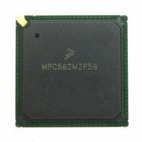
MPC562MZP56 Freescale Semiconductor, MPC562MZP56 Datasheet - Page 78

MPC562MZP56
Manufacturer Part Number
MPC562MZP56
Description
IC MPU 32BIT 56MHZ PPC 388-PBGA
Manufacturer
Freescale Semiconductor
Series
MPC5xxr
Datasheet
1.MPC561MZP56.pdf
(1420 pages)
Specifications of MPC562MZP56
Core Processor
PowerPC
Core Size
32-Bit
Speed
56MHz
Connectivity
CAN, EBI/EMI, SCI, SPI, UART/USART
Peripherals
POR, PWM, WDT
Number Of I /o
64
Program Memory Type
ROMless
Ram Size
32K x 8
Voltage - Supply (vcc/vdd)
2.5 V ~ 2.7 V
Data Converters
A/D 32x10b
Oscillator Type
External
Operating Temperature
-40°C ~ 125°C
Package / Case
388-BGA
Processor Series
MPC5xx
Core
PowerPC
Data Bus Width
32 bit
Data Ram Size
8 KB
Interface Type
SCI, SPI, UART
Maximum Clock Frequency
40 MHz
Number Of Programmable I/os
56
Number Of Timers
22
Operating Supply Voltage
2.6 V to 5 V
Maximum Operating Temperature
+ 85 C
Mounting Style
SMD/SMT
Minimum Operating Temperature
- 40 C
On-chip Adc
2 (10 bit, 32 Channel)
For Use With
MPC564EVB - KIT EVAL FOR MPC561/562/563/564
Lead Free Status / RoHS Status
Request inventory verification / Request inventory verification
Eeprom Size
-
Program Memory Size
-
Lead Free Status / Rohs Status
No
Available stocks
Company
Part Number
Manufacturer
Quantity
Price
Company:
Part Number:
MPC562MZP56
Manufacturer:
FREESCAL
Quantity:
204
Company:
Part Number:
MPC562MZP56
Manufacturer:
Freescale Semiconductor
Quantity:
10 000
Part Number:
MPC562MZP56
Manufacturer:
FREESCALE
Quantity:
20 000
Company:
Part Number:
MPC562MZP56R2
Manufacturer:
RFT
Quantity:
1 441
Company:
Part Number:
MPC562MZP56R2
Manufacturer:
Freescale Semiconductor
Quantity:
10 000
- Current page: 78 of 1420
- Download datasheet (11Mb)
lxxviii
•
•
•
•
•
•
•
•
•
•
•
•
provide maximum system safeguards against hardware and software faults. This chapter provides
a detailed explanation of this functionality.
Chapter 7,
and status.
Chapter 8, “Clocks and Power
the MPC561/MPC563.
Chapter 9, “External Bus
bus.
Chapter 10, “Memory
external memory and peripheral devices.
Chapter 11, “L-Bus to U-Bus Interface
(L-bus) and the unified bus (U-bus). The L2U module includes the Data Memory Protection Unit
(DMPU), which provides protection for data memory accesses.
Chapter 12, “U-Bus to IMB3 Bus Interface
structure is used to connect the CPU internal unified bus (U-bus) to the intermodule bus 3 (IMB3).
It controls bus communication between the U-bus and the IMB3.
Chapter 13, “QADC64E Legacy Mode
(QADC) modules on MPC561/MPC563 devices are 10-bit, unipolar, successive approximation
converters. The modules can be configured to operate in one of two modes, legacy mode (MPC555
compatible) and enhanced mode. This chapter describes how the modules operate in legacy mode,
which is the default mode of operation.
Chapter 14, “QADC64E Enhanced Mode
(QADC) modules on the MPC561/MPC563 devices are 10-bit, unipolar, successive approximation
converters. The modules can be configured to operate in one of two modes, legacy mode (for
MPC555 compatibility) and enhanced mode. This chapter describes how the module operates in
enhanced mode.
Chapter 15, “Queued Serial Multi-Channel
serial multi-channel module (QSMCM) which provides three serial communication interfaces: the
queued serial peripheral interface (QSPI) and two serial communications interfaces (SCI/UART).
This chapter describes the functionality of each.
Chapter 16, “CAN 2.0B Controller
(TouCAN) implemented on the MPC561/MPC563. Each TouCAN is a communication controller
that implements the Controller Area Network (CAN) protocol, an asynchronous communications
protocol used in automotive and industrial control systems. It is a high speed (one Mbit/sec), short
distance, priority based protocol that can run over a variety of mediums.
Chapter 17, “Modular Input/Output Subsystem
consists of a library of flexible I/O and timer functions including I/O port, counters, input capture,
output compare, pulse and period measurement, and PWM. Because the MIOS14 is composed of
submodules, it is easily configurable for different kinds of applications.
Chapter 18, “Peripheral Pin Multiplexing (PPM)
parallel-to-serial communications module that reduces the number of signals required to connect
“Reset.” This section describes the MPC561/MPC563 reset sources, operation, control,
Controller,” generates interface signals to support a glueless interface to
MPC561/MPC563 Reference Manual, Rev. 1.2
Interface,” describes the functionality of the MPC561/MPC563 external
Control,” describes the main timing and power control reference for
Module,” describes the three CAN 2.0B controller modules
(L2U),” describes the interface between the load/store bus
Operation.” The two queued analog-to-digital converter
Operation.” The two queued analog-to-digital converter
Module.” The MPC561/MPC563 contains one queued
(UIMB).” The U-bus to IMB3 bus interface (UIMB)
(MIOS14).” The modular I/O system (MIOS)
Module.” The PPM functions as a
Freescale Semiconductor
Related parts for MPC562MZP56
Image
Part Number
Description
Manufacturer
Datasheet
Request
R
Part Number:
Description:
Mpc562 32 Bit Powerpc Microcontroller
Manufacturer:
Freescale Semiconductor, Inc
Datasheet:

Part Number:
Description:
MPC5 1K0 5%
Manufacturer:
TE Connectivity
Datasheet:

Part Number:
Description:
MPC5 500R 5%
Manufacturer:
TE Connectivity
Datasheet:

Part Number:
Description:
MPC5 5K0 5%
Manufacturer:
Tyco Electronics
Datasheet:

Part Number:
Description:
MPC5 5R0 5%
Manufacturer:
Tyco Electronics
Datasheet:

Part Number:
Description:
MPC5 50K 5%
Manufacturer:
Tyco Electronics
Datasheet:
Part Number:
Description:
Manufacturer:
Freescale Semiconductor, Inc
Datasheet:
Part Number:
Description:
Manufacturer:
Freescale Semiconductor, Inc
Datasheet:
Part Number:
Description:
Manufacturer:
Freescale Semiconductor, Inc
Datasheet:
Part Number:
Description:
Manufacturer:
Freescale Semiconductor, Inc
Datasheet:
Part Number:
Description:
Manufacturer:
Freescale Semiconductor, Inc
Datasheet:


