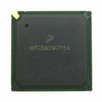
MPC562MZP56 Freescale Semiconductor, MPC562MZP56 Datasheet - Page 1311

MPC562MZP56
Manufacturer Part Number
MPC562MZP56
Description
IC MPU 32BIT 56MHZ PPC 388-PBGA
Manufacturer
Freescale Semiconductor
Series
MPC5xxr
Datasheet
1.MPC561MZP56.pdf
(1420 pages)
Specifications of MPC562MZP56
Core Processor
PowerPC
Core Size
32-Bit
Speed
56MHz
Connectivity
CAN, EBI/EMI, SCI, SPI, UART/USART
Peripherals
POR, PWM, WDT
Number Of I /o
64
Program Memory Type
ROMless
Ram Size
32K x 8
Voltage - Supply (vcc/vdd)
2.5 V ~ 2.7 V
Data Converters
A/D 32x10b
Oscillator Type
External
Operating Temperature
-40°C ~ 125°C
Package / Case
388-BGA
Processor Series
MPC5xx
Core
PowerPC
Data Bus Width
32 bit
Data Ram Size
8 KB
Interface Type
SCI, SPI, UART
Maximum Clock Frequency
40 MHz
Number Of Programmable I/os
56
Number Of Timers
22
Operating Supply Voltage
2.6 V to 5 V
Maximum Operating Temperature
+ 85 C
Mounting Style
SMD/SMT
Minimum Operating Temperature
- 40 C
On-chip Adc
2 (10 bit, 32 Channel)
For Use With
MPC564EVB - KIT EVAL FOR MPC561/562/563/564
Lead Free Status / RoHS Status
Request inventory verification / Request inventory verification
Eeprom Size
-
Program Memory Size
-
Lead Free Status / Rohs Status
No
Available stocks
Company
Part Number
Manufacturer
Quantity
Price
Company:
Part Number:
MPC562MZP56
Manufacturer:
FREESCAL
Quantity:
204
Company:
Part Number:
MPC562MZP56
Manufacturer:
Freescale Semiconductor
Quantity:
10 000
Part Number:
MPC562MZP56
Manufacturer:
FREESCALE
Quantity:
20 000
Company:
Part Number:
MPC562MZP56R2
Manufacturer:
RFT
Quantity:
1 441
Company:
Part Number:
MPC562MZP56R2
Manufacturer:
Freescale Semiconductor
Quantity:
10 000
- Current page: 1311 of 1420
- Download datasheet (11Mb)
R
case to ambient thermal resistance, R
a heat sink, change the mounting arrangement on printed circuit board, or change the thermal dissipation
on the printed circuit board surrounding the device. This description is most useful for ceramic packages
with heat sinks where about 90% of the heat flow is through the case to the heat sink to ambient. For most
packages, a better model is required.
The simplest thermal model of a package which has demonstrated reasonable accuracy (about 20 percent)
is a two resistor model consisting of a junction to board and a junction to case thermal resistance. The
junction to case covers the situation where a heat sink will be used or where a substantial amount of heat
is dissipated from the top of the package. The junction to board thermal resistance describes the thermal
performance when most of the heat is conducted to the printed circuit board. It has been observed that the
thermal performance of most plastic packages and especially PBGA packages is strongly dependent on the
board. temperature.
If the board temperature is known, an estimate of the junction temperature in the environment can be made
using the following equation:
where:
If the board temperature is known and the heat loss from the package case to the air can be ignored,
acceptable predictions of junction temperature can be made. For this method to work, the board and board
mounting must be similar to the test board used to determine the junction to board thermal resistance,
namely a 2s2p (board with a power and a ground plane) and vias attaching the thermal balls to the ground
plane.
When the board temperature is not known, a thermal simulation of the application is needed. The simple
two-resistor model can be used with the thermal simulation of the application (2), or a more accurate and
complex model of the package can be used in the thermal simulation. Consultation on the creation of the
complex model is available.
To determine the junction temperature of the device in the application after prototypes are available, the
thermal characterization parameter (Ψ
measurement of the temperature at the top center of the package case using the following equation:
where:
The thermal characterization parameter is measured per JESD51-2 specification published by JEDEC
using a 40 gauge type-T thermocouple epoxied to the top center of the package case. The thermocouple
Freescale Semiconductor
θJC
is device related and cannot be influenced. The user controls the thermal environment to change the
T
T
R
P
T
T
Ψ
P
D
D
J
B
J
T
θJB
JT
= T
= T
= thermocouple temperature on top of package (°C)
= board temperature (°C)
= power dissipation in package (
= power dissipation in package
= thermal characterization parameter
= package junction to board resistance (°C/W)
B
T
+ (Ψ
+ (R
θJB
JT
x P
x P
D
D
)
)
MPC561/MPC563 Reference Manual, Rev. 1.2
θCA
JT
) can be used to determine the junction temperature with a
. For instance, the air flow can be changed around the device, add
Ω
)
66-MHz Electrical Characteristics
G-5
Related parts for MPC562MZP56
Image
Part Number
Description
Manufacturer
Datasheet
Request
R
Part Number:
Description:
Mpc562 32 Bit Powerpc Microcontroller
Manufacturer:
Freescale Semiconductor, Inc
Datasheet:

Part Number:
Description:
MPC5 1K0 5%
Manufacturer:
TE Connectivity
Datasheet:

Part Number:
Description:
MPC5 500R 5%
Manufacturer:
TE Connectivity
Datasheet:

Part Number:
Description:
MPC5 5K0 5%
Manufacturer:
Tyco Electronics
Datasheet:

Part Number:
Description:
MPC5 5R0 5%
Manufacturer:
Tyco Electronics
Datasheet:

Part Number:
Description:
MPC5 50K 5%
Manufacturer:
Tyco Electronics
Datasheet:
Part Number:
Description:
Manufacturer:
Freescale Semiconductor, Inc
Datasheet:
Part Number:
Description:
Manufacturer:
Freescale Semiconductor, Inc
Datasheet:
Part Number:
Description:
Manufacturer:
Freescale Semiconductor, Inc
Datasheet:
Part Number:
Description:
Manufacturer:
Freescale Semiconductor, Inc
Datasheet:
Part Number:
Description:
Manufacturer:
Freescale Semiconductor, Inc
Datasheet:


